Smart Switch Installation Guide for 1 Switch Module
Ready to upgrade your home with smart technology but unsure where to start? Don't worry; we've curated a comprehensive guide to ensure your installation of the 1S smart switch is smooth and hassle-free. Follow these detailed steps for a seamless and smarter living experience!
Installation Essentials:
Before you begin, gather these essential tools and materials:
- Insulated screwdrivers (star or flat)
- Insulated pliers
- Voltage tester
- Wire strippers
- Multimeter (optional)
- New smart switch
- Insulation tape
- Appropriate wires (based on load and requirements)
Ensure you have everything ready to proceed smoothly with the installation of your 1S smart switch.
Safety Tips for Smart Switch Installation:
- Read the smart switch instruction manual thoroughly.
- Turn off the main circuit breaker and double-check with a voltmeter.
- Use insulated tools and wear protective gloves.
- Clearly label all wires for easy identification.
- Ensure your workspace is dry and organised.
These steps will help ensure a safe and successful installation of your smart switch.
Module Compatibility and Console Box Specifications:
When preparing to install the 1S smart switch, understanding its compatibility and console box requirements is crucial for a successful setup:
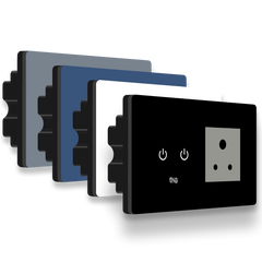
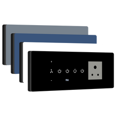
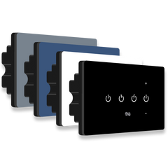
Module Name: 1S
Console Box Size: 78 mm x 78 mm (3" x 3")
Module Specifications:
- High-Load Switch (H): 16A
Installation and Wiring Guide:
- Turn off the power at the breaker box.
- Label the phase, neutral, earth, and other load wires in the wall console box.
- Study the terminal labels on the product's wiring sticker to ensure correct wire connections.
-
Connect the wires to their designated terminals as indicated below:
- Neutral (N): Powers the device.
- Phase 1 (P1) UPS/EB: Primary power supply.
- Phase 2 (P2) EB: Alternative power source or looped with P1.
- High-Load (H): Manages high-wattage devices.
- Check the wiring setup video for your specific type at home. Ensure all connections are correct, secure, and free of loose strands.
- Use insulation tape to secure exposed terminals and wire joints.
- Use a prying tool to carefully remove the glass panel without touching the circuit board.
- Insert the enclosure into the 2-module metal console box and secure it using the provided screws (M3.5*30mm).
- Align the top glass with the enclosure and press it firmly to lock it in place, ensuring that all four corners are securely locked.
- Restore power and test the switch for proper functionality.
If you need any device installation support or assistance, please call or WhatsApp.
Wiring Setup Scenarios:
Type 1: Single Power Source (EB or UPS and Common Neutral)

- The phases for EB and UPS will remain separate.
- The neutral line will be common for both EB and UPS.
-
In the above scenario, the phase and neutral connections will be as follows:
- The UPS or EB phase is connected to P1, providing power to the device.
- The UPS or EB phase is also connected to P2 (looped from P1), providing power to the high load (H).
- The common neutral will be connected to N.
Type 2: Additional Customization for High Load Output Using External Relay (Common Neutral)

- The phases for EB and UPS will remain separate.
- The neutral line will be common for both EB and UPS.
-
In the above scenario, the phase and neutral connections will be as follows:
- The UPS or EB phase is connected to P1, providing power to the device.
- The UPS or EB phase is also connected to P2 (looped from P1), providing power to the high load (H).
- The common neutral will be connected to N.
- To externally control high loads through an existing power switch (e.g., from H, 6A), add a 40A relay for external supply control.
-
In the above scenario, the connections for the relay will be as follows:
- The phase for the relay is from H.
- The relay IN is directly connected from the DB phase.
- Then the relay OUT is connected to the AC load.
- The common neutral (N) will be connected for both the relay and the AC load.
Note: Implement this solution only with accurate information from the official technical support team.