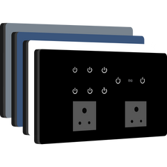
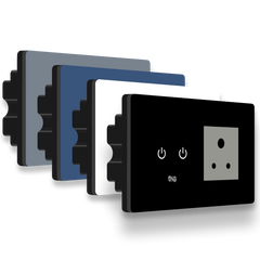
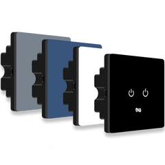
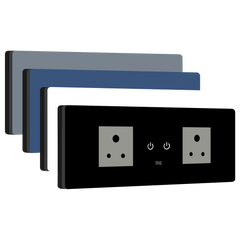
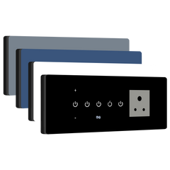
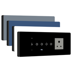
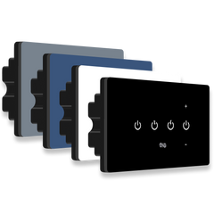
Wiring instructions for our 8 Module devices
IMPORTANT NOTE:
- Always connect the primary power source to P1 Terminal
- Only one Neutral connection is available.
Case 1: Single Phase & Single Neutral
In Single Phase and Single Neutral scenarios, Loop P1 & P2 and connect the Phase to the P1 terminal and connect Neutral to the N terminal.

Case 2: Double Phase (UPS Phase & EB Phase) & Single Neutral
Connect the UPS Phase to the P1 terminal. Connect the EB Phase to P2 terminal and connect Neutral to N terminal.

Case 3: Triple Phase (UPS Phase, EB Phase & AC Phase) & Single Neutral
Connect the UPS Phase to P1 terminal. Connect the AC Phase, i.e. Air Conditioner Phase to P2 terminal. Connect Neutral to the N terminal and then Insulate the EB Phase.

Load Wiring
To connect loads, just follow the connections as shown in the image below or the instructions at the back of the device with Smart Switches.

Video Guide on wiring our 8 module devices

